
The increasing frequency for as-built point cloud scans as part of the delivery of a project is a sign that clients are no longer willing to rely on design models unchecked and issued as record information. However, the approach that contractors are taking is a reactive one which fails to make use or take the full benefit of the technology.
What is construction verification?
Verification during construction is not new. The positions of building components have always been checked by traditional surveying methods, whether that is using a total station or a tape measure. Software verification is different because it seeks to verify every component’s position using computing power, instead of the small subset that traditional methods can check.
Like many technologies, this step change has been enabled by the wide adoption of other technologies. In this case, the increasingly common use of BIM and the low cost of mass data collection using laser scanning provide the reference model from the designer or fabricator and a point cloud snapshot of the current state of the build as scan data.
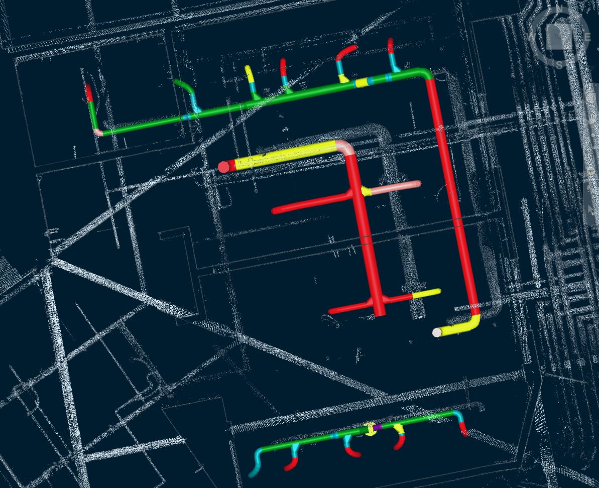
The core of the verification process involves comparing the registered laser scans against a model; the result provides visual and statistical feedback on the comparison. There are currently two types of verification process. These can be characterized as geometry-only or contextual verification.
The first compares geometry alone to the point cloud and reports on the statistics of the match. This can be applied to anything, including complex geometry. Reporting for these verifications is more difficult because the data is in a raw form and needs to be interpreted. The second usually makes a comparison of specific elements of a project: for example, the flatness of a floor. Reporting is more straightforward in contextual verifications, and is sometimes measured directly against a standard for that construction type that governs expectations for flatness or tolerance, for example.
So where are people going wrong?
The software itself is straightforward to use; it performs the verification once data has been collected then combined with the model. The problems arise because of poor briefing by clients and unplanned or reactive site work. Nearly every project I have been involved with has suffered from both of these issues.
Getting the specification right
At one end of the spectrum, briefs may be as ambiguous as simply specifying ‘verification’ and referring to the purpose of the activity as ensuring that the as-built model is accurate. At the other end, unrealistic expectations that either exceed construction tolerances or the capability of hardware or economic survey activities are common.
Consider this: performing a verification of 5 mm from a point cloud on data that is reliable to +/-15 mm is meaningless. While local scans can have better accuracy than this, positional verifications of less than 25 mm at whole-building scale deliver questionable results. For service installations, which often deviate from their design locations substantially, it is sensible to consider greater distances of 100 mm.
As with many new functions in digital construction, the question of what is specified should relate to the purpose of the exercise. Most client specifications expect verification to establish where design models need to be updated so that the as-built models are correct. In practice, the response to this can seem to come at the end of a project, which runs the risk of some components being covered up. Large elements such as wall layouts, steelwork, ducts, sheet metal cable trays and larger pipe runs are verifiable with software, but cage-type cable trays, flex ducts which differ from the model and smaller pipework are either not verifiable or impractical at any scale because of the density of the point cloud. In these situations, falling back to visual verification from the point cloud data is necessary as an alternative approach requires this. There are also a lot of materials (particularly in service installations) which laser scanning doesn’t capture well. Black glossy painted drainage and silvered ductwork are examples.
Late reactive verifications have another common problem: positioning the laser scan data to fit the model. Near to the end of a project, the control network that the building was set out from has often been removed or concealed. In this situation, the verification can only be performed by a ‘best fit’ approach to positioning the scan data. This is less reliable because it is a relative positioning, instead of an absolute positioning to the original setting out coordinate system. It is also more labour-intensive and therefore more costly.
Each of these issues can be overcome by planning the verification, and as with every workflow, the right time to plan is at the beginning of the project. A reactive verification at the end of a project is simply a cost item, whereas well-planned verification can repurpose this requirement to the benefit of the smooth running of the construction programme.
Why verify during construction?
There are several additional advantages to performing a verification during construction. It can be used to establish if components are built out of position and will subsequently cause problems with follow-on packages. Early recognition of this sort of conflict allows time to decide whether a package needs to be re-positioned, or whether the follow-on package can accommodate the new position. It also gives a snapshot of what has been built at that point, and identifies components that are in the model but not yet built, which provides valuable support to the valuation process.
We are at another point in the timeline of the industry where a group of factors have come together to disrupt and change the way that we work. Clients’ expectations for accurate as-built information, verification software and powerful computing, and a new generation of scanning total station hardware, have made the site-to-software pipeline rapid and largely automated. A planned verification during construction is both more economic and more valuable; it provides trackable benefits to the project, and delivers the foundation for accurate as-built models.
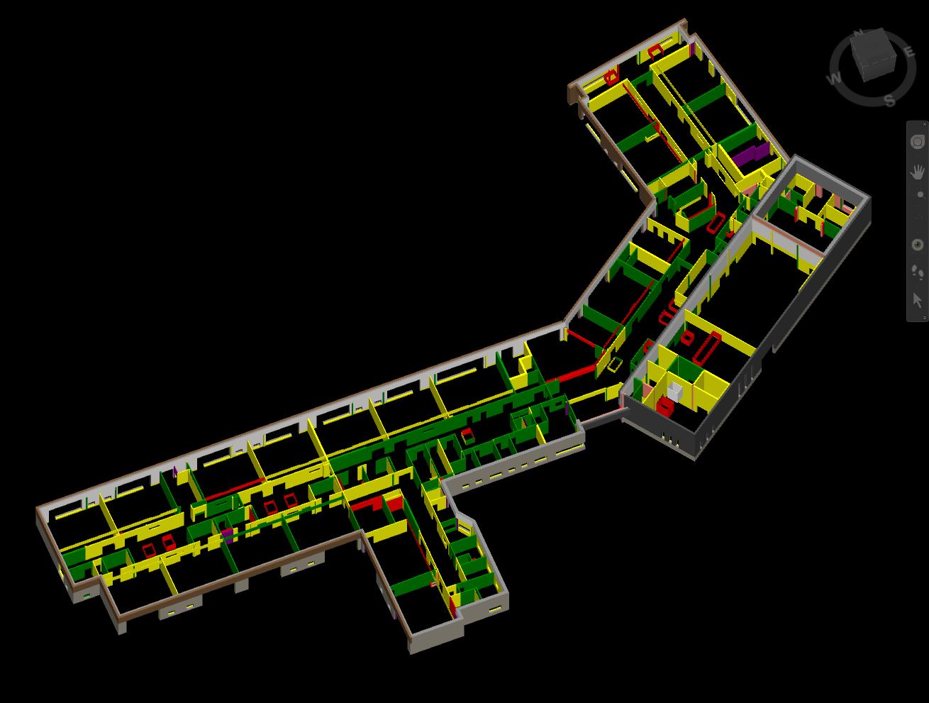
This image shows an area of the as built model where the services layout differ substantially from the design model. This will need to be updated.