
Coordinating information
On larger construction projects, it is not unusual for a project team to produce in excess of 1,000 drawings and over 1,000 pages of specifications. With this in mind, it is an understandably daunting task to coordinate the annotations displayed on the drawings with the information in the corresponding specification.
In recent years, modelling tools have made the task of coordinating the information between individual drawings sheets far more manageable. For example, if a window is removed from a 3D model, then this window is also removed from each drawing sheet and schedule that it is displayed on.
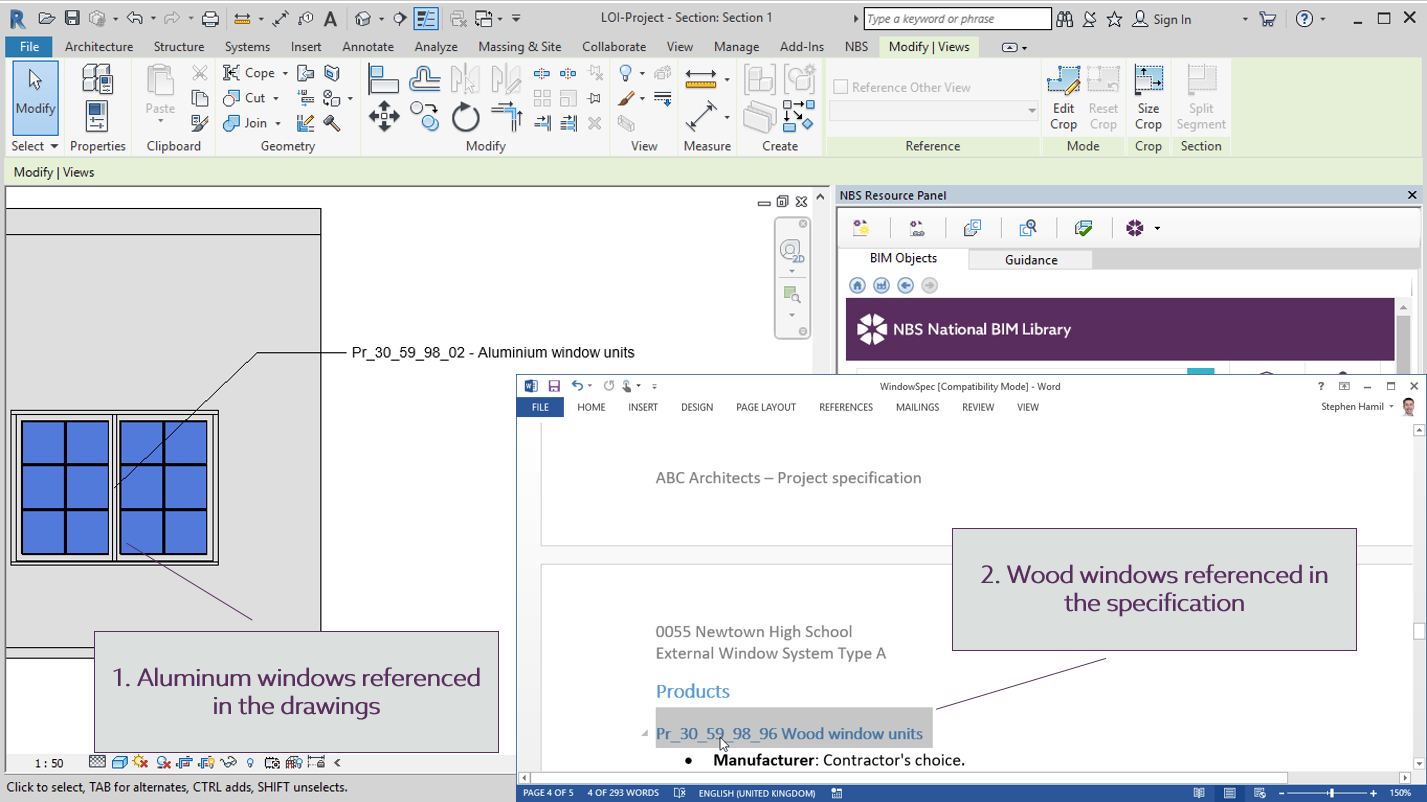
What is proving to be a challenge is when the specification changes after a project has begun. A client may change their requirements, or cost consultants or planners may provide new information that results in designs changing. When this happens it is critical that any changes are reflected throughout all relevant data sources. Figure 1 below, shows an example where this information is badly coordinated: an aluminium window is displayed in the drawing and a wood window is described in the specification. This problem of badly coordinated project information is a costly one for the industry.
A standard classification system such as Uniclass 2015 may be used for both specification and modelling. This allows items to be referenced through a classification code by title and type code.
Standard codes allow all members of the project team to generate a consistent set of project documentation. When a project has a common approach to its annotations, the task of verifying and cross-referencing information becomes a more manageable. Where this is digitalised then software functionality allows this task to be automated.
NBS are launching NBS National BIM Library for Australia, where each object has common properties for information that is typically added to a model. At an international level, the IFC classes and associated property sets are added to objects. IFC properties include key performance properties such as acoustic, fire and durability ratings. These are ideal for scheduling information and colour-coding drawings. Additionally standard COBie properties for information handover are also added. COBie properties include key handover and maintenance information. This will range from a manufacturer name to contact details, product references, installation dates and defining an expected life. Furthermore, internationally used classification codes from Uniclass and OmniClass are included. This means that each type of object has a standard template of information structure with blank values for generic objects. Proprietary objects are filled with region-specific values provided by manufacturers.
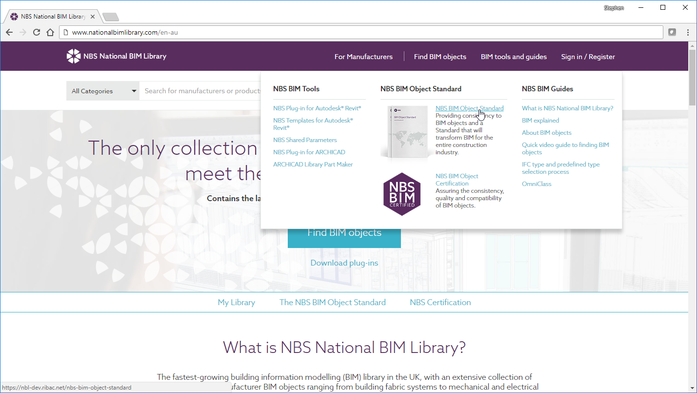
The focus on standardized information and a consistent approach means that each object in the National BIM Library is certified to this BIM Object Standard. This is one of the unique features of this library of objects from NBS. By focusing on the information associated with the objects, users gain more benefits than simply drawing generation and clash detection. Standardised information also makes the task of coordination significantly easier and lowers project risks.
Have a plan
Design is an iterative process and the information required and generated grows through the project timeline. Across the items in a built asset, not all information will be generated at the same rate. Certain externally visible parts of the asset may need to be fully designed to receive planning approval. Conversely, other items may be left as a simple specification description and indicated spatial zone at an early stage and then developed through to a performance specification for contractor design once the building contract is awarded.
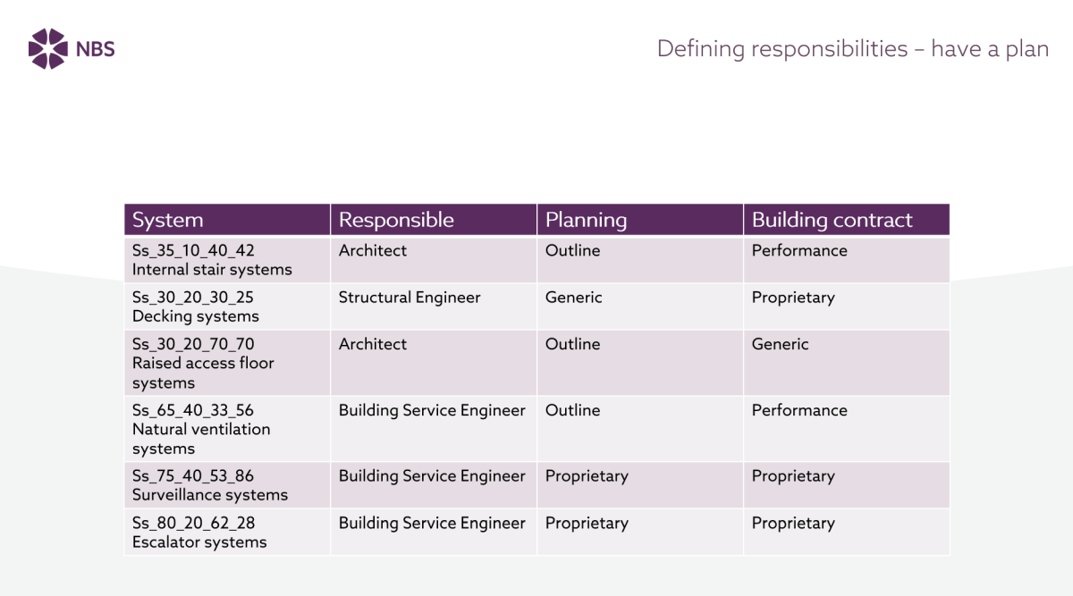
It is crucial that the project team comes together to plan these responsibilities and this information development early in the project. For BIM projects, this responsibility matrix should be in response to the employer’s information requirements. It would typically be included in the BIM Execution Plan and be updated throughout the life of the project as design decisions are agreed. Figure 3 shows a simplistic design responsibility matrix indicating information development for key stages of the project.
The right level of information at the right time
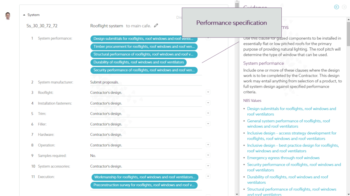
The screenshots below shows that a well-structured master specification system can provide a home for specification content as it develops through the project timeline. Figure 4 shows an outline description of a system such as a rooflight. This could be a simple description outlining the design intent in response to a client’s brief.
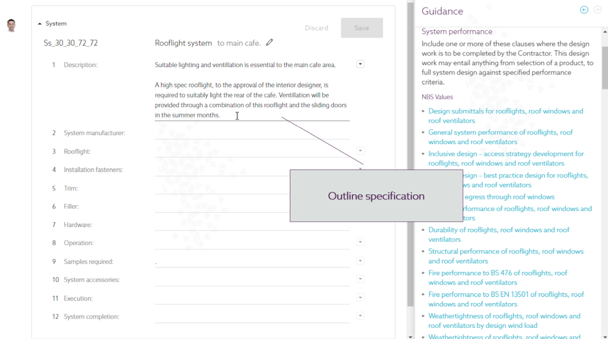
Figure 5 also focuses on a rooflight system. In this scenario, the components of the rooflight such as the unit, fasteners, trim and hardware have been identified as contractor’s design. Specification clauses have however been invoked to describe the required system performance, the information requirements for the design submittals and also the quality of execution expected.
Many projects nowadays have a contractor design portion. It is critical that drawings and specifications are provided that sufficiently define this work.
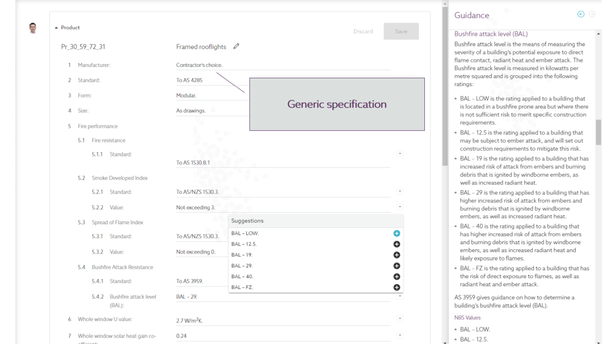
Quite often certain product selection decisions are left to the contractor, however a tight generic specification defines the requirements. In Figure 6 below, a generic specification prescribes the requirements for the framed rooflight unit. The final manufacturer and product reference decision has been left to the contractor, providing that this selection meets the criteria.
If submittals or samples are required to verify product selection prior to construction, this should be documented in the specification.
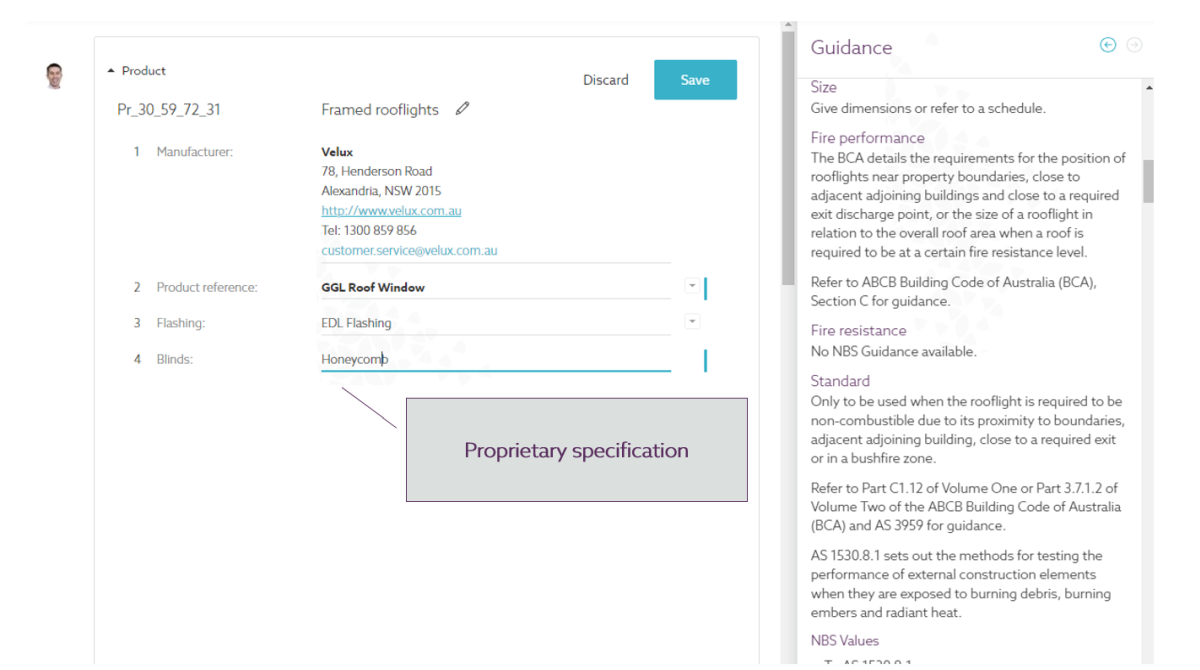
Finally, there will be times when a designer specifies a particular product. In this situation the specification may be reasonably short, the manufacturer’s details, the product reference and any product specific options may be all that is needed. In Figure 7 a proprietary specification for a rooflight unit is shown.
A flexible system for specification, where different items within the built asset can be specified to different levels of information as the project progresses, provides the flexibility that is needed on complex construction projects. Throughout this process it is vital that the project team collaborate so that there is an understanding of who is responsible for developing particular information and to what depth.
Where a standard system is used for classification and annotation, then this method of working can be used to coordinate the information set across the project documentation.
Further reading