This article is an adaption of the joint presentation by Stephen Hamil and Alistair Kell, at Autodesk University London. Alistair is Principal at BDP with responsibilities for information, technology and process. Stephen is Innovation Director and Head of BIM at NBS.

Introduction
A recent publication on construction from the McKinsey Global Institute reported that the industry has made little productivity improvements in the last 60 years. Over the same time period, other industries such as agriculture, manufacturing and retail have all seen major improvements. This study’s conclusion was that productivity can be greatly improved by focusing on a number of action areas. The action area predicted to have the largest benefit for construction was ‘infusing’ digital technologies into construction processes. The report predicted that this would cause a 14–15% improvement in industry productivity.
However, when considering how we build better to meet with future demand, productivity and cost savings are not the only factor. With respect to building a safer built environment, the Hackitt Report in the UK (commissioned to review the Grenfell Tragedy) recommended that there should be a legal responsibility for the handover of a ‘digital record’ for those leading the work on high-rise residential buildings.
So time and time again, it is concluded that digital technology is the answer to improve productivity, quality and safety, as the industry rises to meet the challenge of the worldwide need for greater construction.
Preparing for the project
Before considering technology on a digital project, it is essential to prepare and plan for the work itself. One of the main tasks is to develop a design responsibility matrix in response to the project’s exchange information requirements. At an early stage, on a typical project, it is very unlikely that every item within a building is known. Figure 1 below shows that a sensible level for design responsibility matrices is two or three deep in the Uniclass 2015 Systems table. In this example, taken from a BDP primary school project, the responsibilities for Door and window systems and Roof covering systems are assigned. Good practice at this stage is to consider how the specifications will be packaged, and whether a performance specification (to inform the Contractor’s design) or a full specification will be required. In the BDP example, naming conventions for the output files, as they will be viewed in the common data environment, are also considered.
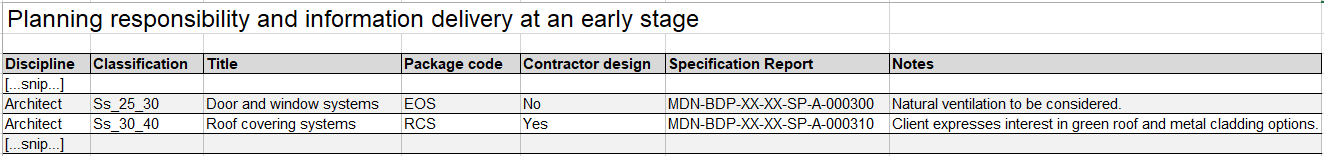
Figure 1 – Before the design begins, the responsibilities are agreed
Figure 2 below shows how these items are then developed further as the concept design progresses. The specification can start to be assembled once each of the specification types is known. Having an office policy on naming convention of type codes also helps. In the example below, it can be seen that all roof covering systems have a type code starting with ‘RCS’ and then have a three-digit consecutive number. These codes, in combination with the specification classification and title, can then be used for cross-referencing in all of the coordinated documentation.
Clearly, the examples here demonstrate two aspects of the project for one of the disciplines. The real power of correct preparation is demonstrated when this is a cross-discipline exercise and a standard method of working is agreed, and documented in the BIM Execution Plan, for the whole team. Experienced clients can influence this method of working in the initial exchange information requirements. An example of a design responsibility matrix can be downloaded from the RIBA Plan of Work website; in addition, this content can be managed online using the NBS BIM Toolkit. Both of these resources are free to use.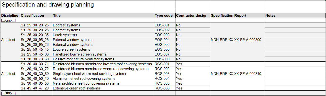
Figure 2 – As the design progresses, the types of systems are agreed
Design and specification
Many practices are now using modelling tools such as Autodesk Revit or Graphisoft ArchiCAD to generate their drawings and schedules from a single source of information. When considering the wider documentation set, and specifications in particular, it is important to ensure that the information on the drawings and schedules is coordinated with the project specification.
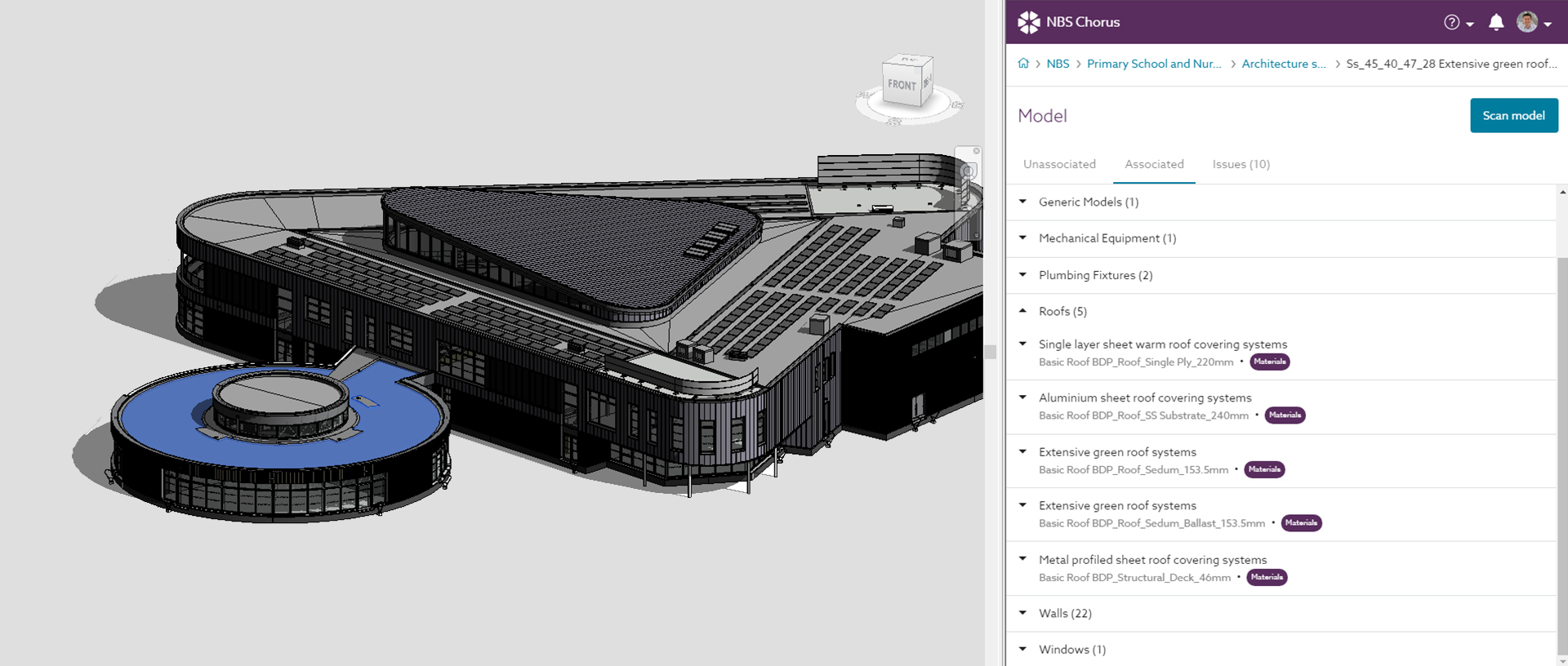
In video sequence 1 below, the BDP primary school project has its architectural model linked to its specification in NBS Chorus. It can be seen that the type codes and classifications for the roof covering systems all match those defined at the preparation stage. This provides clarity and transparency for the project team.
Through a permissions model, the specification can be accessed by all relevant members of the project team on the cloud. The level of information in each specification can be developed, based on the responsibilities agreed in the appointment. So for this specific example, performance specifications may be developed for the roof covering systems, and full specifications may be developed for the door and window systems.
Video: Coordinate, and contribute to, the specification from the design environment (63 seconds)
Construction and handover
The video sequence below shows that it is possible, in NBS Chorus, to export all of these submissions into a file format that may be uploaded to leading common data environment solutions from Autodesk, Viewpoint and Newforma. In the example below, the testing and inspection certification for a flat roof system is assigned to a sub-contractor. Each of these submissions is referenced back to the specification that will specify the precise level of information required in this documentation.
Video: Export submittals from the specification into the common data environment (1m 56s)
Final thoughts and useful links
The industry is embracing digital processes and the momentum is now unstoppable. Examples in this article have shown how leading practices such as BDP are developing information throughout the project timeline, from preparation stage through to handover.
The video sequence below shows where the industry is heading. When drawings, schedules and specifications are progressively developed throughout the timeline and are shared following the processes outlined in the BS EN 19650 series of standards, then a transparent digital audit trail is created.
Video: An audited trail of transparent decisions throughout the project timeline (2m 36s)
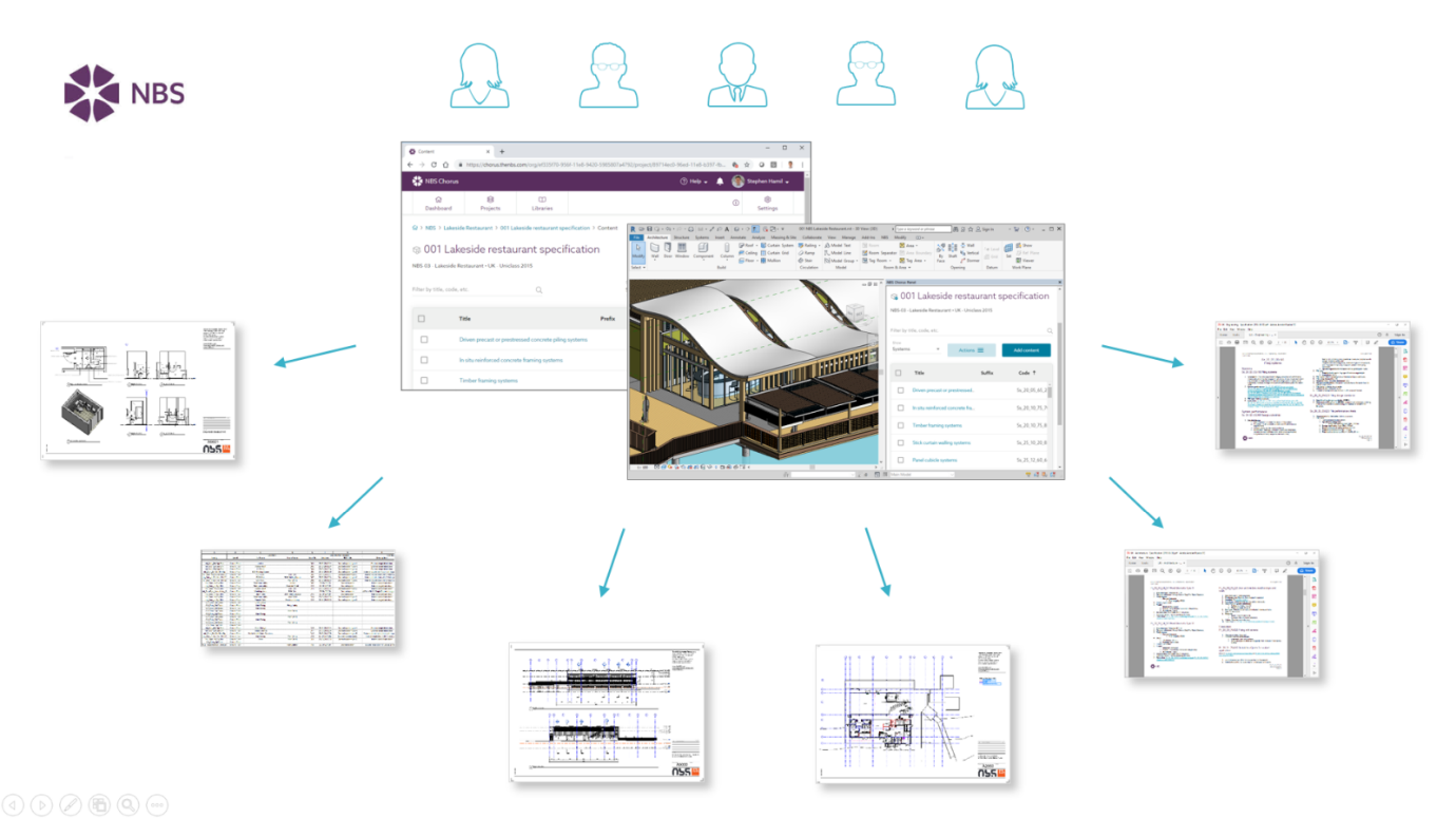
The optimum workflow is one in which drawings and schedules are generated from a 3D design model. This model is integrated with the specification and developed in parallel to produce a coordinated set of documentation that can then be used, and against which checks can be made, in the next stage of the project.
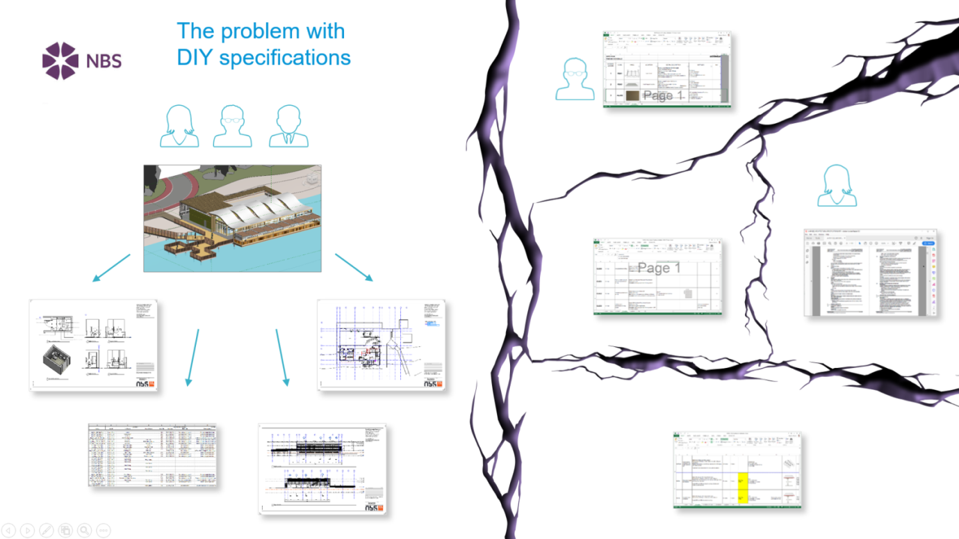
Figure 3 shows the risk of uncoordinated documentation, and compares it to the coordinated set of documentation indicated in Figure 4.
To learn more about the subjects covered in this article, follow the links below:
- Uniclass 2015 – Uniclass, the classification for BIM projects to ISO 19650.
- NBS National BIM Library – free-to-use generic and manufacturer BIM objects from NBS.
- NBS Chorus – cloud specification platform for architects and engineers.
- BDP and BIM – find out more about BDP and their BIM process.
Watch the presentation
Watch the full presentation from Stephen and Alistair (as delivered at Autodesk University London 2019) at the Autodesk website below: